Wiring Resistance
Contents
What does this mean on a real track?
What does this mean to my cars?
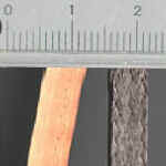
Tape and braid - the same width but very different in resistance
|
Wiring Resistance Contents What does this mean on a real track? What does this mean to my cars?
|
Tape and braid - the same width but very different in resistance |
Page last updated 2021
Part 5 of this series of articles says what should be connected to where - and gives a simple guide to how to wire it. This page gives the reasons for the recommended wiring and explains how different thicknesses of wire and ways of connecting it make a difference.
There is a separate article explaining how to find and repair track wiring faults.
What do you wire a slot track with? - well OK with wire obviously but what type. The important factor is the cross sectional area of copper, which dictates the resistance. (The current ratings given in wire tables are not relevant) Yes it does need insulation, but any insulated wire will do (it only needs to withstand about 14 volts). There are special cables available (at considerable expense) which are intended for Hi-Fi loudspeakers - these may do something for the nuances of musical reproduction, and will certainly do something for your HI-Fi retailers profits. Yes there are small changes in resistance depending on the wire (the resistance of copper does change a little with impurities; fully annealed copper has nearly 4% less resistance than fully hard). High quality 'oxygen free' speaker cable can be well over double the the cost of an equivalent thickness mains cable, but its resistance is only very slightly lower - if you are going to spend twice as much, spend it on twice as much mains cable and halve the resistance - what really counts is how much copper you get
for your money! Normally the cheapest suitable wire available is mains cable. Each core is usually a single strand of copper, so its suitable for fixed wiring (for your controller you need flex - where each care is made of many strands of thin wire).This advice is correct for the prices of cable in the UK, I don't know what prices are charged for cable in other countries. However, wiring up mains power in buildings is bound to be a much larger market for cable than more specialist uses in any part of the world, so I assume that cable for wiring building would be the cheapest source of cable with reasonably large cross sectional area in most if not all countries.
|
The Resistance of Copper Conductors |
|||
|
Conductor |
Area sq.mm |
Resistance ohms per meter |
Notes |
|
Copper lane tape 0.25 x .005 inch (approx 6.4mm x 0.1mm) |
0.8 |
0.021 |
Should be stretched when laying. The availability of these thicker sizes of tape is currently a problem. |
|
Copper lane tape 0.25 x .004 inch (approx 6.4mm x 0.1mm) |
0.64 |
0.027 |
|
| "1.5 mil" copper tape 0.25 x .0015 inch (approx 6.4mm x 0.06mm) | 0.24 | 0.071 | Self adhesive tape available from glazing suppliers. Typically used on top of rails on plastic track. Most makes shouldn't be stretched when laying. |
| "1 mil" copper tape 0.25 x .001 inch (approx 6.4mm x 0.04mm) | 0.16 | 0.11 | |
|
Tin plated copper track braid (typical 6mm wide x 1,5 mm thick) |
effective area 2.5 |
0.007 |
|
| Tin plated copper track braid (typical 6mm wide x 1mm thick) |
effective area 1.75 |
0.010 | |
| Tin plated steel braid (typical 6mm wide x 1mm thick) | 0.080 | Steel braid is used to give magnet traction on routed tracks, steel is lower conductivity than copper | |
|
Mains lighting cable |
1.0 |
0.017 |
|
|
"13 Amp." Mains Flex |
1.25 |
0.014 |
|
|
Ring Main Cable (2.5mm2) |
2.5 |
0.007 |
|
|
Cooker Cable (6mm2) |
6.0 |
0.003 |
|
|
18 AWG wire |
0.823 |
0.021 |
|
|
16 AWG wire |
1.31 |
0.014 |
|
|
14 AWG wire |
2.08 |
0.008 |
|
|
12 AWG wire |
3.31 |
0.005 |
|
Shorter wiring has less resistance - half the length has half the resistance. Double the cross sectional area has half the resistance - so paralleling up two core of a cable will half the resistance. The table above shows the approximate resistance of various conductors used in track and controller wiring. (The resistance of nominally similar copper wire does vary due to various factors, but this is a detail that is unimportant to track wiring.)
(If you want an equation, ohms law tells us the voltage drop = resistance x current and resistances add up as shown below)
What does this mean on a real track?
The best way to answer this is to work out the figures for a typical track. The example I’ve used is a 30m / 100 ft. lap length track - the exact figures will vary with different lap lengths, but the principles are always the same. The resistance varies round the lap length. The graphs show how the resistance between the car and the track power supply vary as you drive round the track. A greater the length of track between the car and the power feeds, gives more the resistance and hence the less power. As the graphs show, the highest resistance is mid way between the power feeds, but the resistance changes very little for some way either side of the halfway point . The reason for this is that as the car goes round the track the resistance from the previous feed is
going down - these two just about cancel out round about the half way point.There is also some resistance in the wiring between the battery, the controller sockets, and the point where power is feed to the track. This is why the graphs don't drop to zero resistance at the power feed point. (The graphs assume 0.05 ohms between the power supply and the tape / braid where the power is feed in. Again this is typical of a good club track)
| Resistance in ohms between the car and the track power supply |  |
| Graph 1 - The Resistance of Tape and Braided Track with a Single Power Feed |
The Graph 1 shows a comparison between tape and braid. It clearly shows that the resistance of braid is much lower than tape. In this example a 10 amp. load half way round the lap would see about 1.5 volts less than the battery voltage on the braid track. The same 10 amp. load would see about 4.6 volts less than the battery voltage on the tape track.
Given a reasonable battery, the braid track op to about 30m / 100 ft lap length should meet BSCRA recommended power levels with the power feed in at one point.
The tape track certainly does not meet BSCRA recommended power levels with the power feed in at only one point - indeed it doesn’t even meet the BSCRA minimum level. A Group 12 powered car would be noticeable down on power, a hotter motor even more so. However, a 1 amp. load would only cause a drop of 0.46 volts, so extra feeds make much less difference to low powered cars such as Falcons (and the extra feeds make even less difference to Scalextric, Ninco etc. cars) .
The answer to this lack of power on a tape track is to add extra power feeds. The resistance for tracks of different lap lengths will be in proportion to their lap lengths - for example double the lap length, double the resistance; half the lap length, half the resistance. The graph for a single feed will always be the same shape with the highest resistance half way round the lap length.
Graph 2 shows the improvement that can be achieve with an extra feed or 2 on the tape track. (I’ve assumed the extra feeds are 3 metres of 2.5sq.mm cable fed from the main power feed. On a real track extra feeds would probably be all different lengths, but this example gives a reasonable idea of what's going on in most tracks). The example shows that a couple of extra feeds will reduce the highest resistance to a little over 0.2 ohms - a voltage drop into a 10amp load to a little over 2 volts - a big improvement on the 4.6 volts with only a single feed, but still not as good as braid.
Graph 3 shows the improvement obtained on the taped track with 4 or 5 feeds (the main feed and 3 or 4 extra feeds). I’ve shown braid on the same graph It can be seen to that tape with 5 feeds gives broadly similar levels of power to braid with a single feed.
|
|
||
|
Graph 4 Resistance of Tape with a Break on One Side (3 feeds) |
||
Feeding power to both ends of a length of tape reduces the resistance substantially. Graph 4 shows what happens to the resistance with a single tape break. the rise in resistance would be much worse with one break on each side.
What does this mean to my cars?
OK, so how much does all this matter - is the effect of all these tiny bits of resistance going to mess up your racing? There are tracks that most racers consider "good power" and there are other tracks where the power attracts complaints. BSCRA rules do recommend power levels (10 amps at 12 volts) and set a minimum (4 amps at 12 volts). I’ve measured the power on many tracks. The tracks with a reputation for "good power" meet BSCRA recommendations (at least most of the way round). The tracks people complain about are usually well short of BSCRA recommended levels and some are below the minimum. BSCRA rules do not specify track resistance, but if you start with a battery or power supply at 13.8 volts ohms law tells us that to get at least 10 amps at 12 volts the resistance must be under 0.18 ohms (and for the minimum power level the resistance must be under 0.45 ohms. ) This 0.18 ohms includes the resistance of the battery itself, so perhaps its advisable to aim for a bit less resistance in the track wiring.
Using the above figures, with "good power" a 26g strap motor accelerating from low speed will only see about 10.2 volts -and a Group 12 accelerating from low speed will see about 12 volts. At the minimum level a 26g strap motor accelerating from low speed will only see about 7.2 volts -and a Group 12 accelerating from low speed will see about 10 volts.
The same principles apply to plastic track, but the main problem with this type of track is often continuity at the joints due to the connections deteriorating. The rails of plastic track do have resistance (for example Scalextric Classic track rails have a resistance of about 0.039 ohms/meter) but this is less of a problem with the very much lower current motors that are usually used on this sort of track.
Chris Frost
| Building the track surface | |
| Cutting the slot | |
| Painting, laying braid or tape | |
| Lap Counting | |
| Wiring | |
| Back to Track Building start page |
Copyright © 2000 to 2001C Frost Minor updates included 2002, 2005, 2007, 2009, 2012, 2015, 2018, 2021 All rights reserved
No liability is accepted for the information on this site or any use to which it may be put