Contents of this page
Link to Next Page - Cutting the slot

Assembling the "UK Black" Track
TRACK CONSTRUCTION Part One
|
Contents of this page
Link to Next Page - Cutting the slot |
|
|
Assembling the "UK Black" Track |
by Chris Frost
Updated April 2009
Right then, you’ve got this great track design, designed with the help of (or in spite of) the track design web pages. How do you go about building it? If you’ve got the funds track builders like Steve Ogilvie in Canada or the Lars Harrysson in Sweden will do the job for you. If not the only option is to build it yourself.
I’m assuming that your club has enough practical skill to handle the power tools safely and do a reasonable carpentry job. I would hope it goes without saying, if you don’t know how to do a job safely DON’T DO IT!
I’m setting out to describe how many good tracks have been built. No doubt there are many other ways of building tracks - so if you know another way of producing a good track then good luck to you (and why not write into Slot Car Racing News and describe how you did it). I’m also trying to describe the advantages and pitfalls of various techniques - but I’m sure I cannot have thought of everything.
There are two types of board most suitable for the surface of slot car tracks ; MDF (medium density fibre board) and chipboard. Chipboard was the traditional material but is little used in the last couple of decades, it produces an adequately smooth surface, and is the cheaper option. MDF has been used for most routed tracks built in the last couple of decades , it produces a smoother surface and a smoother slot, it is better structurally. MDF is a little heavier, but perhaps thinner sheet can be used. The minimum thickness for the track surface is 12mm (1/2 inch), although if you are using chipboard, a greater thickness is an advantage. Not all MDF is created equal, the light weight lower density grades are not as satisfactory for track building as the higher density grades. It's a good idea to talk to your board supplier to select a suitable grade, and if a supplier doesn't understand the question go elsewhere! The good stuff may well cost a bit more but its is much better value if you are keeping the track for a few years.
The "standard size" for board is 2.4m by 1.2m (8 ft. by 4 ft.) sheets. Smaller sheets are available, but are almost always much worse value for money. Joints between sheets make extra work and tend to cause bumps so smaller sheets are not a good idea. Its worth shopping around for board - the first do-it-yourself superstore you come across may well be expensive, particularly compared with the prices paid by someone "in the trade".
The board that forms the track surface will sag under its own weight unless some support is provided. The traditional way of doing this was to put wooden battens underneath - a piece running lengthways each side and cross pieces every 40-60 cm. (16in - 2ft,) some tracks used 25x50 mm (2x1 inch) timber, but this was a bit too flexible, and 75mm (3in) depth was more satisfactory. Timber tends to expand and contract with temperature and humidity changes at roughly the same rate as the surface boards, so there is limited warping problems. More recently MDF surfaced tracks have been built using strips of MDF on edge in place of the timber. This has the advantage that the track is all of one material so it shouldn't warp. Its likely to work out cheaper because there are usually plenty of bits of MDF that are too narrow for track surface, but are usable in the supports. I don't recommend using chipboard in this way, it isn't very satisfactory in this sort of structural application. Incidentally one disadvantage of MDF strips compared with timber is that wood screws only work well into the thickness of MDF, it tends to de laminate if screws are put in edgeways so the screw fixings are a bit weak (although nothing like as weak as screws edgeways into chipboard). The professionals used pinned and glued construction on MDF with extra reinforcing blocks (see diagram A). You can use a metal frame under the surface , but you have to allow for different expansion rates to avoid warping.

The above construction is great for straights, but obviously needs a bit of adaptation for corners. One approach is to carry supports on in straight lines (see right hand part of diagram B) The other is to build structural curved edges to the track - these will double as crash barriers. You are not going to be able to bend a 12mm strip of MDF round a tight radius - the secret of this is to use 3 thicknesses of 4mm MDF glued together (see diagram B). If this is done properly the finished job will look just like a curved piece of 12mm thick strip. (To get a good finish use slightly wider 4mm strips and cut it down to the finished width when the glue has dried.)
Unless you plan to run your track on the floor, (Some HO events are run with the track on the floor) the track needs to be supported at a suitable height. There are various conventions on what is the correct height - 8 lane tracks tend to be at about knee height rather than the normal British club track just below waist height.
What do you use to support the track?
One answer is to use anything which is cheap, available and reasonably rigid. For a permanent tracks I’ve seen tables, cupboards, work benches, oil drums (clean and empty!) in use. These all worked and the clubs got them for little or no money because they were in the right place when the original owners were scrapping them. A fair bit of adjustment with packing is usually needed to get the levels right, but as long as the track isn’t going to be moved then this is a job that only needs doing once.
Some clubs have bolted up a "Dexion" frame - this is likely to be a costly option unless you can reuse some Dexion being put in a skip. If you don’t manage to recycle somebody else's surplus then what do you do?
Many clubs have built a timber frame. An adequate timber frame does not need particularly high quality craftsmanship although there are some well built ones around. (Save the real skill for the track surface!)
 |
The supporting timber frame for the Haydon track taken during construction. |
Some clubs have used welded steel frames - this is only an option for clubs with a welder and a supply of cheap steel. Users of metal frames should beware of the differing rates of expansion of steel and wood. Unless the surface is able to move relative to the frame, warping and cracks are likely.
What about tracks that are not set up permanently? Perhaps there are tables available in the room where the track is used - if so the track won’t need its own legs. If the track does need its own legs then they need to be easy to fit, remove and store.
A good design of track leg is the type used on Steve Ogilvie’s tracks. I don’t think I’m giving away too many trade secrets here as lots of tracks are built around similar lines. Diagram C shows how these legs work. Each leg is made from a pair of triangular pieces of 12mm (half inch) plywood. The two pieces are bolted together with a single bolt - 10 mm is about the right size. The top piece is then bolted to the track - 3 bolts of say 6mm diameter will do this job nicely. A slot in one piece of plywood allows the complete leg to be adjusted in both height and angle (to adjust for slight banking). This means that once the track is set up the level and gradients can be adjusted easily. These legs allow the track to expand and contract along its length, so there is little risk of distortion with temperature and humidity changes. Clubroom floors are rarely either level or flat so some adjustment in the legs is necessary even if the track is perfectly built. It the track is in a fixed location there is something to be said for using a wood screw or two to lock the two halves of each leg together. For transportable tracks this may not be such a good idea, as the next floor its put up on will have the bumps in different places from the last one.

A 4 lane track under construction showing the adjustable plywood legs
The track surface will be made up of several sheets of board. These need to be joined together so that the top surface align. Its as well to aim for a perfect fit, but obviously some tolerance is needed. Diagram D shows the sorts of imperfection in the joints that can occur. (The diagram exaggerates the size of the imperfections for clarity.) The following sizes are what a really good track should have. Steps in the track upset the cars more than gaps. The slightest step up at the joint must be avoided. If you cannot achieve perfect level, then a slight step down ( say 0.1mm .004inch) won’t be a problem. Obviously a step up in one direction is a step down in the opposite direction, so if you plan to race on the track in the reverse direction steps need to be avoided. Gaps between sections look worse than steps, but are less of a problem to the car. Ideally there should be no gap between the sections. However the car won’t notice gaps the thickness of a couple of sheets of paper. The other type of imperfection is a change in gradient. As the articles on track design explained, cars don’t like convex changes in gradient, so avoid them. A slight concave change will do no harm (providing that it doesn’t result in a convex transition somewhere else) I know one track where there was a concave transition from horizontal to about 1 in 25 gradient at a track joint, This was too sudden for this sort of transition and it caused the cars to ground and jump about at the joint. Eventually they decided to make a smooth transition so there was no instant change of gradient - this was a popular improvement with visitors and home members alike!
Its likely that joints will get worse with time, so very accurate joints when the track is built should mean it’ll be a lot longer before any serious maintenance is needed!
Are there some tracks around that are not this good? Yes there certainly are! Some seem to work OK and some attract complaints. Cars are not sensitive to imperfect track joints if they are
(a) traveling slowly or
(b) heavy
(c) on straights
(d) have loads of ground clearance
(e) are 1/24
(f) are not F1s
(g) are low powered
(h) are not being driven on the limit.
So if you are cruising round with a 1/24 retro-slot car you won’t be inconvenienced much by bad track joints on slow straights (nor will you benefit much from excellent track joints!)
So how do you go about constructing these joints? It all depends on how often the track is going to be assembled and taken apart. If the track is going to be built in the club room and is never going to be taken apart the sheets can be screwed to a continuous supporting structure with overlapping pieces of sheet. Then fill the joint and sand it smooth before painting.
If the track is going to be taken apart and set up for a few days at a time, then it needs to be constructed so it’ll go together correctly. Typically a well built large transportable track (For example the BSCRA Nationals track) can be put up in a few hours and taken down in a hour. A portable track - one that is going to be put up and taken down every club night needs to be up and running in 10 or 15 minutes.
If the track is going to be built in the club room and will never come apart then simple joints such as shown in diagram E will work well. Even if the track will never be moved, you will need access to maintain the track under the bridge - so design in a removable section.
Perhaps the simplest way of joining sections for a portable track is to build in a batten (or strip of MDF) under the joint; get the surfaces level; clamp the battens together, drill holes for two dowels and two bolts. (See diagram F) The dowels should be a tight fit - lots of tracks use dowels about 12mm or 1/2 inch diameter. The bolts should be a loose fit, 8mm or 5/16 inch are typical sizes for this job. I’ve seen a lot of tracks with dowels for location - You might think it would be an easy way of providing perfect location. Most of the dowelled joints I’ve seen don’t work very well - the usually start to jam so need to be filed down - so they don’t locate very well. Indeed there’s more than one portable track where all but one of the troublesome dowels were dispensed with. They relied on the people assembling the track to get the correct height correct across the width of the track surface and then tighten the loose fitting bolts. By resting a hand across the joint to feel when its flat, some people can its set up each joint accurately in a few seconds.
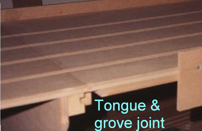
A tongue and groove construction such as diagram G works well on transportable track. The professionally built tracks such as Steve Ogilvie have a double tongue and groove arrangement along similar lines. The tongue and groove arrangement produces a simple strong joint. The bolts should be a loose fit in the holes - they are there to clamp the two sections together - bolts should not to locate them. As all this is made of MDF it will all move together if there is a change in humidity or temperature.
Chris Frost
| Next - Cutting the slot | |
| Painting, laying braid or tape | |
| Lap Counters | |
| Back to Track Building start page |
|
What is chipboard? This sheet material is know by other names in some countries. Any timber merchant or DIY store in the UK knows it as chipboard. It is know as particle board in some countries (to add confusion, particleboard is sometimes used as a general term to include flakeboard, strandboard and wafer board as well as chipboard) . Chipboard consists of chips or particles of wood a few mm in size bonded together with an adhesive under pressure. The top and bottom surface are hard and smooth. The core has voids between the chips (see the close up photo) and is quite weak once the outer surface is removed. The photos on the right shows what chipboard looks like. MDF appears to be called MDF all over the world. |

 |
Copyright © 1989, updated 1999, 2000, 2009 ,2024 British Slot Car Racing Association All rights reserved
No liability is accepted for the information on this site or any use to which it may be put.