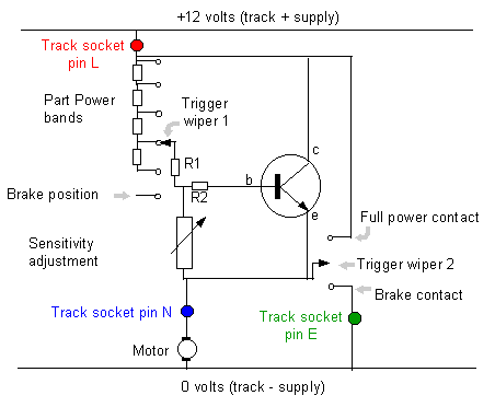
The "normal British" circuit uses the PNP type of power transistor, these imported controllers use the NPN type of power transistor. These two types of transistors work in a similar way except the electrical current passes in the opposite direction. They are both "linear" circuits which means that at part power they reduce the power to the car by turning the unwanted power into heat. Either circuit will produce exactly the same amount of heat when driving the same car at the same speed. So both types need the same size of heat sink (and cooling fan) to keep the transistor at the same temperature. They both work in a very similar way, so once you understand how one works its easy to see how the other one works. I've used a different way of describing the workings of the two type, hopefully that'll help some readers understand it more easily (although there's always the risk of doubling the confusion!)
A completely different type of transistorized circuit is used in switching controllers.
The NPN circuit
There are two separate wipers (both mounted on the trigger
arm in the controller). Wiper 1 controls the current to the base of
the transistor. Wiper 2 provides full power and brake. (In some
controllers wiper 2 is the Parma full power and brake contacts
rather than a wiper as such. Some controllers have a full power
relay added).
The sensitivity adjustment is usually a knob on the controller handle that
can be dialed up to get the desired setting.
R1 and R2 are alternatives, the circuit will work with one or the other.
Some controllers have a "choke" adjustment - this is a variable
resistor in place of R1.
To keep the diagram simple, I've shown just 4 part power bands,
controllers have got more bands. Also I've shown a chain of fixed
resistors, some controllers have adjustable resistors at each step and
some have plug in modules with different resistance values.

The transistor is only working when the controller is on part
power. At full power and brake the transistor does not pass any
current (unless there's a fault).
A small current passes from b (base) to e (emitter), this controls
the much larger current that goes from goes from c (collector) to e (emitter).
By choosing the right resistors to control the small current to the base,
the much larger current going to the motor is controlled
. I suggest those of you who are not mathematically
inclined skip the next bit and look at "What does this tell us?"
The voltage drop in the controller when it's on part power can be calculated By using ohms law and simplifying it a bit by assuming the current going to the base is negligible, the answer comes out as

The transistor doesn't turn on till the b to e voltage is greater than about 0.6 volts. So if we use exactly 0.6 in the above equation, it becomes.

Where VLN
=The voltage measured between pin L and pin N
Vbe = the voltage measured
between the base and emitter of the transistor
Vband =The total resistance of the resistors in the
part power band from the wiper to pin L
R1 is the resistor shown on the diagram
Vsen = The resistance of the sensitivity adjustment
resistor
When the controller is on part power (normally during cornering)
The voltage drop is never less than 0.6 volts. (and it will be more
unless R1 is a very low value)
Moving the wiper up the part power band so that there are more resistors
in circuit will increase the voltage drop in the controller. (So moving
the trigger changes the voltage going to the motor.)
Increasing the sensitivity adjustment resistance decreases the voltage
drop in the controller. (Also the sensitivity adjustment makes more difference
when the trigger is in a low power position than when it is close to full
power)
Increasing the resistance of R1 will increase the voltage drop in the
controller (so an adjustable R1 will act as a "choke" control).
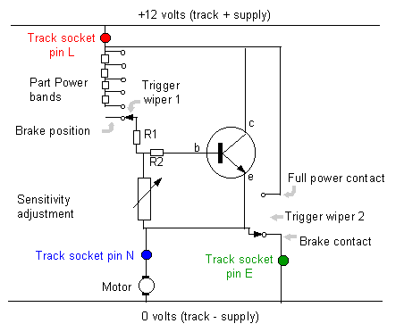
Here's the diagram redrawn with the wipers in the brake position.
Trigger wiper 1 is not connected to anything. The base of the transistor is connected to the emitter via the sensitivity adjustment resistor and R2. This means that the base and emitter are at the same voltage, so the transistor will pass no current.
Trigger wiper 2 is connecting pin N direct to pin E, a normal brake connection just like any controller.
Note that on brake the transistor collector is still connected to the L pin, so if there was a fault causing current to leak to the base, the transistor would get warm when the controller was on brake.

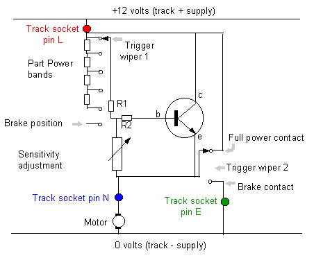
Here's the diagram redrawn with the wipers in the full power position.
Trigger wipers 1 and 2 are connected to pin L. This means that the base, collector and emitter are all at the same voltage, so the transistor will pass no current. As alternative that would work equally well is for Trigger wiper 1 not to be connected to anything. Here again the base, collector and emitter are all at the same voltage, so the transistor will pass no current.
Trigger wiper 2 is connecting pin N direct to pin L, a full power connection just like any controller.
Note that on full power all 3 terminals of the transistor are connected together, so it will still work on full power even with a transistor fault.

In many ways it is quite similar except
This NPN circuit uses a single transistor not a "Darlington pair", with a single transistor the voltage drop is never less than 0.6 volts, with a "Darlington pair" there are two transistors in series so the voltage drop is never less than about 1.2 volts.
The NPN circuit needs two isolated wipers connected to the trigger where as a circuit using PNP transistors needs just the single wiper. (The base of an NPN transistor needs to be connected to pin N to turn off when the controller is on brake. The base of a PNP transistor needs to be connected to pin L to turn off when the controller is on brake.)
In most ways they are the same except the NPN circuit needs two isolated wipers connected to the trigger where as a circuit using PNP transistors needs just the single wiper.
If all you want to do is replace this 1.2 volt drop with 0.6 volt, why go to the extra complication of two isolated wipers then PNP transistors can be used.
These circuits don't have any over current protection. If there is a short circuit on the track, the full power goes through the transistor. The way round this is to use a transistor with a really high current rating. In the past the transistor industry only makes really high current rating transistors in NPN, this is still true to some extent, but PNP transistors such as the MJ14003 will take 60 amps. A look at a couple of electronic supplier's catalogues showed several NPN types with current ratings in the range 60 to 100 amps.
Could you use several transistors in parallel to add up to a really high current rating? Well yes you could BUT it's not likely to work well because transistors rarely share current equally when simply connected in parallel, and as they heat up the sharing becomes less equal. (They could be made to share current much better by putting 0.1 ohm resistor in the emitter lead of each transistor).
I'm afraid so!
The b to e voltage isn't exactly 0.6 volts. It decreases as temperature increases. It increases as current increases. It is not identical in all transistors (not even in a pair of the same part number transistor).
I simplified the examination by saying the current going to the base is
small compared with the current passing through the sensitivity adjustment
resistor. If the base current is significant, then the voltage drop
from the + voltage to the base will be larger. Hence the voltage
drop across the controller increases as the base current increases. This
depends on the size base current relative to the emitter current. The
ratio between these currents is known as the gain of the transistor, if
you look in tables of transistor properties it's often listed as "hfe".
This might be 1000 to 2000 for a "Darlington pair" and 80 to 150
for a single transistor.
Taking a couple of examples with a motor taking 5 amps and the controller
on part power. For a "normal
British" circuit the base current is 2.5 - 5 milliamps, with 100
ohms this makes 0 .25 to 0.5 volts difference in the voltage
drop to the base. For one of these NPN the base current is 33.3 -
62.5 milliamps, with 25 ohms this makes 0 .83 to 1.56 volts difference
in the voltage drop to the base.
The gain isn't fixed. It changes with temperature increases.
It changes with current running (in some cases reaching a maximum at 5 -
10% of the maximum rated current, and much less as the power rises). It is
not identical in all transistors (not even in a pair of the same part
number transistor).
So do all these extra complication matter?
The changes with temperature do mean the controller characteristics
will change as it warms up. This doesn't seem to cause slot car
drivers a practical problem, possibly because drivers are used to compensating
for the car characteristics changing during a race and the transistor
heating doesn't change the controller characteristics all that quickly.
The driver adjusts the controller to suit the car he is using, which is
pretty much depends on how much current the motor needs in each
corner. So the driver will adjust the controller to suit the
current that motor actually takes and also compensate for the differences
between one transistor and another (even though he doesn't realize turning
the knob on the controller is doing all those things at once).
A good circuit design text book would tell designers to avoid circuits
that depend on the exact value of the base - emitter voltage drop or the
gain of the transistor precisely because they are variable. These
controller circuits do depend on these characteristics. but practical
experience shows they work well enough!
Some readers will have spotted that these rather variable characteristics
are reasons why simply paralleling up a pair of transistors doesn't
work very well.
Do car characteristics changing during a race?
Yes they do! Some examples of what changes - Tyres grip better once
they are warmed up, armature resistance goes up as it warms up, cars
handle better as the tyres wear down. The biggest change I've
measured is on tracks with rather old fashioned power supplies where the
battery voltage dropped from 13.5 volts to 12.5 volts during a race.
The drivers didn't notice this change - presumably they just braked a bit
later and pushed their controllers down a bit more in corners as the race
progressed.