Electronic Controllers
How they work and How to keep them working reliably
updated June 2009, minor chages October 2018
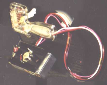 SCD trigger controller
How do Transistorized Controllers Work
There two main types of transistorized controller circuit - liner and switching.
Among the most commonly used linear circuits are the "normal British" circuit (which uses a PNP Darlington pair of transistors) described below on this page, the single PNP transistor equivalent (such as Paul Bucknell's design) and the single transitor NPN circuit often used in imported controller (click on this link for a description). There are some other designs which offer some advantages, but I'm not going to attempt to explain how these work.
Diode controllers, sometimes called passive electronic controllers such as the Cidex Omi, Slotworks Speed Gun and some Professor Motor controllers work on a different circuit.
A completely different type of transistorized circuit is used in switching controllers, examples of these are TruSpeed and SlotIt
The "normal British" circuit
Most of the transistorized controllers made in the UK use variations on the same circuit (SCD, Streakers powerqrip, Slotwiz plus many Ece, Parma, Manhandle conversions and scratch built controllers from Ian Fisher, Nick Evans, Birdseed, Sid Jensen, Dave Clutterbuck etc.) There are lots of other transistorized circuits that could be used, the following applies to this commonly used circuit. Difalco and PRO2 controllers work on a different transistorized circuit design.
I hope the following explanation will be understandable to most readers. (and even if it isn't, the page on good ways to blow up transistors (and how to avoid them) should be useful!)
The circuit diagram (below) is typical "normal British". This circuit allows adjustment of the controller to suit the car:- it's relatively simple (simpler = less to go wrong and easier to work out what to fix it if it does go BANG! However, there is no protection against excess currents damaging the transistor.
I've said the diagram above is a typical circuit, what variations are there? The number of steps in the resistor chain varies - some early examples had 6 steps, 10 or 12 is more common, and SCD offer a 24 step board. The resistors in the chain “R” are usually all the same value - various builders choose different values. The resistance of the pot (variable resistor) 'VR' and the total value of all the resistors in the chain need to be in proportion to each other. So double the pot resistance needs double the R resistance, twice as many steps mean each r should be half the resistance. value Here are some typical values-
| The pot (variable resistor) 'VR' value | Chain resistors "R" with 10 - 12 steps | Chain resistors "R" with 20 - 25 steps |
| 100 ohms | 33, 47 or 56 ohms | 15, 22 or 27 ohms |
| 250 ohms | 82, 100 or 150 ohms | 47, 56 or 68ohms |
The resistor 'r1' is often 33 ohms, some builders leave this one out (in which case the last part of the pot movement doesn't do anything useful). The resistor “r2”' can be between 10 and 100 ohms. “r2” controls the size of the 'bottom step' of the controller and limits the base current to the transistor. To give a smaller "bottom step', “r2” can be deleted and replaced by “r3”as shown below.
In theory to be absolutely safe 'r2' or 'r3' should be large enough to limit the base current to the transistor to it's safe current limit, (that is at least 15 ohms for a MJ11015) in practice 'r2' of 10 ohms seems to work OK. The transistor is usually an MJ11015, (this is strictly speaking a pair of transistors in one package - a Darlington pair, to use the jargon). This is the best choice of the normally available transistors for the purpose, although for lower powered cars and tracks, you might get away with a lower power/heat rating and cheaper transistor.
The
alternative 3 transistor arrangement shown works in the same way - two
transistors Q1 and Q2 share the main current (mostly a pair of TIP2955
transistors) and a third transistor Q3 (usually a TIP42) controls the other two.
It is unlikely that Q1 and Q2 will share the current equally (and once
they start to heat up, the sharing
will become
less equal)
so to
get the equivalent
power handling
ability to
a single MJ11015
(30 amps/ 200
watts), you need Q1 and Q2 with somewhat more than
just half that rating - a TIP2955 (15 amps/ 90 watts) doesn't
quite meet that - you'd be better off with a TIP 36.
On paper the MJ11033 offers more current and power dissipation (50 A and 300w) than the widely used MJ11015 (30 A and 200w), so it looks like a better choice for this circuit. The extra current and power isn't needed in normal circumstances, but should withstand track shorts etc. better. I would add I've not tried it, so any feedback from anybody who has would be welcome.
So how does it work? When the transistor is passing a current the voltage drop from “e” (emitter) to “b” (base) is reasonably constant. The voltage drop from “e” (emitter) to “c” (collector) adjusts to suit the circumstances. The voltage drops down a chain of resistors (in series) will be proportional to their resistances. Ignoring the current passing to the base of the transistor, the resistors on the left hand side of the circuit diagram are a chain of resistors in series, so the voltage drop will be in proportion to their resistance. Now, as the voltage drop from the emitter to the base of the transistor is constant, the total voltage drop across the controller will be the same as the ratio of the resistances.
![]()
Transistor connections - TIP42 on the left and MJ11015 on the right. The TIP2955 and TIP36 have the same connections as a TIP42. You won't find E, B and C marked on the case - transistor manufacturers aren't that helpful to people who don't understand their products!
The examples below show how this works (I've simplified the real circuit and chosen some simple numbers for clarity). In the example below note that the ratio between the resistances is the same as the ratio between the voltages.
If the plunger is released a couple of steps (examples below) the resistance of the chain increases, this causes the voltage drop to increase, so the motor goes slower. Hence the motor goes faster is you press the plunger down and slower as you lift off.
If the pot is adjusted to a lower value (right hand example above) its resistance is a smaller proportion of the rest of the chain, this causes the voltage drop to increase, so the motor goes slower for each plunger position. Hence the motor goes faster throughout the controller movement if you twiddle the knob to increase the pot resistance and slower of you turn it the other way. Also you can see that these controllers are controlling the voltage drop, not the current.
In fact this explanation is a bit over simplified, some current does flow from the base of the transistor and the emitter to base voltage does change a bit with current (as well as temperature) so the current will make some difference. The graph (below) shows how an actual controller behaves with different loads.
This was measured at the plug with the plunger on the top step, (there will be different curves for each combination of plunger position and pot adjustment but they will all be the same general shape). A true variable voltage device would appear as a horizontal line on the graph and the controller would have been more like this if measured right next to the transistor. Unlike the transistorized controller, the voltage drop across a variable resistance controller is proportional to the current - I've drawn a couple of examples on the graph. So how does the transistorized circuit compare with a traditional variable resistance controller and with diode controllers? Full power is limited by the full power contacts and wiring whatever type of controller you've got, so differences really only apply on part power - when the car is cornering.