Electronic Controllers

What's different?

If you are used to a resistance controller, here's some thoughts on what's different using an electronic controller
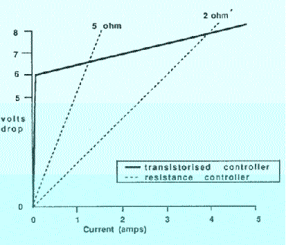
              The transistorized (and Diode) controller will suit motors of widely different current rating on the same setting.  People tell me that some Scalextric / Fly / Ninco cars are driven on the same setting as a saloon G12. Look at the graph  below (measured on a Streakers controller) shows, an identical setting behaves like a 2 ohm controller with a motor taking 4 amps and a 5 ohm controller with a motor taking 1.3 amps.   (however this isn't really that much of an advantage - transistorized controllers are adjustable anyway)

ii           With a transistorized (and diode) controller its less noticeable it you've got two cars on your lane. 
Looking
at the graph, doubling the current changes the transistorized controllers voltage drop by 10-15% for circuits using a Darlington pair (like the "normal British" circuit) and perhaps  more with some single transistor circuits).
A second car on your lane isn't likely to be very noticeable switching type transistorized controllers
.
Doubling the current changes the resistance controllers voltage
drop by 50% so the second car on your lane is much more noticeable.
iii                Linear transistorized (and diode) controllers make the  car  more  sensitive  to  fluctuation  in power supply  voltage. Single transistor circuits (like the NPN one I've described) tend to be a bit less sensitive  to  fluctuation  in power supply  voltage than ones using a Darlington pair (like the "normal British" circuit)
Resistance controllers and
switching type transistorized controllers are less sensitive to  fluctuationin power supply  voltage.
(Hopefully  today’s  tracks  have fairly  consistent  power  supplies  so  this  is not as noticeable as it used  to be.)
vi             Transistors  only  work  with  the  current flowing in one direction, resistors will work with it going either  way.   If you have a resistance controller this doesn't matter.    If you have a "dual polarity" transistorized controller this doesn't matter.   Most transistorized controllers (including the PNP and NPN circuits described on this site) won't work and will probably by damaged by reversed track polarity.   This isn't a problem with tracks wired  to BSCRA standards and controllers sold for BSCRA racing - they are all the same polarity.  However, some home tracks and many home sets are wired with the opposite polarity. 

 A diode only passes current one way, but some diode controllers  use pairs of diodes (bridge rectifiers) so that they will work either way round.  It is much less likely that a diode will be damaged by connecting it the wrong way round.  (But follow the manufactures instructions - better safe than get an unexpected big bang!)

v             Most linear transistorized   (and   diode)  controllers control  the  speed  of  the  car  where  as  variable resistance controllers (and a few transistorized designs) control  the power (that is speed multiplied by torque).  When you lift off from full power the transistor / diode will slow the car more  rapidly  than  with  a  resistance,  this  was claimed to be a great advantage by one diode controller supplier,  but nobody seems to have noticed their transistorized  controller  has  the  same characteristic.

vi       The  step  between  the  bottom  band of  a normal transistorized controller and full  power  is  quite large.  The ones I've measured using a Darlington pair (like the "normal British" circuit) show about 2 volts.  The minimum size of  this step is limited by the transistor,  it may be possible to choose resistor values to reduce  it to about  1.4 volts.  Other circuits  (like the Paul Bucknell design or the NPN one I've described or circuits using MOSFETs) can halve the size of this bottom step. In some circumstances  a  large  bottom  step  could  be  an advantage, but there may be an advantage in being able to adjust this value which is exactly what the "choke" control on some controllers does.  
A large bottom step may not be a good idea for almost but not quite flat out corners sometimes found on raceways - you just might want to drive with less than full power but more than the bottom step allows you.
 
A diode controller will have a bottom step of about 0,7 volts or 1,4 volts depending on if it has I or 2 diodes in the circuit. 
Switching type transistorized controllers generally use a completely different type of transistor (called a MOSFET) which allow the bottom step to be very small.

vii     Transistorized controllers are more complicated - so there is more to go wrong, and if something does go wrong it is lot difficult to work out what. (Still you might have a better chance if you understand how it works!)

viii    When the car is trying to pick up through a film of oxide on the tapes, so there is no current flowing for an instant, what you need is as many volts  as  possible  to  break  down  the  oxide.  A controller  that  applies  the  full  power  supply voltage in these conditions, even when your thumb (or finger) is part way down,  can be a significant advantage. Some  of  the  early  attempts  at  transistorized controllers didn't do this and caused the cars to be more sensitive to bad pick up.  As the graph shows, this  circuit  does  not  suffer  from  this problem. Switching type transistorized controllers don't suffer from this problem.
(This is a potential problem with some diode controllers.)
ix    There are large differences between the quality of design and build between controllers that employ the same basic circuit – these are often more important than the basic circuit itself.


Back to controller start page

The circuit normally used in British controllers

Good ways to blow up controllers

(and how to avoid them)

The alternative Circuit often used in imported controllers
  Switching Controllers


Copyright © 1996 to 2015 C.Frost All rights reserved

 No liability is accepted for the information on this site or any use to which it may be put.