NOTE - This diagrams omits switches, fuses etc. Click here for the full instructions on track wiring.
This page is no longer maintained - go to the controller index for the up to date pages
Why Do I Need a Controller?
| Slot cars need to full motor power at the beginning of a straight - braking at the end of a straight and reduced power to go round a corner. A controller allows you to do just that. |
|
Full power is just a question of connecting the power supply to the tapes - and hence to the motor. An on-off switch would do this bit! The less resistance at full power the faster the car will go - so low resistance contacts and thick wire help. For ultimate performance a full power relay may help. In some circumstances, it is an advantage to have less then full
power. This is provided by a "choke" - usually an adjustable
resistor with a resistance of a small fraction of an ohm. Link
- how to connect a choke |
|
Brakes Brakes are achieved by connecting the motor terminals together. This makes the motor act like a dynamo and slows itself down quickly. The less resistance on brake the sooner the car will stop - so low resistance contacts and thick wire help. This is called "Dynamic braking". In the very early days of slot racing controllers didn't have brakes, so the cars just coasted to a halt slowed only by friction, some home sets are still made this way. Many drivers find reducing the braking effect can improve the drivability at some circuits. The controller can easily provide variable brakes by inserting a variable resistor between the brake band and the negative supply. Lower resistance give more braking. Link- how to connect a brake box |
|
Cornering Reducing power for corners is the main area where controllers have developed in recent years. The normal method of reducing the motor power is to waste some of the power as heat. All resistance controllers, all diode controllers and most transistorized controllers work this way. Traditionally a variable resistor has been used to reduce power. This usually consists of many turns of resistance wire wound on a ceramic former, with a wiper making contact direct on the resistance wire. Up till the late 1980s this was the only technology generally available. It worked pretty well, and when the resistor suits the car you are driving the advantages of anything more complicate are marginal . The major disadvantage is that one resistor didn't suit all cars and all tracks. Too low a resistance and you cannot go slow enough round some corners - in extreme cases (e.g. Scalextric car on 5 ohms) you end up with something not much better than an on-off switch! Too much resistance and all the action happens too near the full power - in extreme cases (e.g. Group 12 car on 25 ohms) you end up with something not much better than an on-off switch again! Some people had several different controllers - Some people found ways of adjusting the resistance - but the problem was really solved by the introduction of transistorized controllers which were very widely used by the early 1990's. There is more on resistance controllers here. There is an alternative approach to all this hot stuff - that is to switch the power on and off very quickly - if this is done fast enough (say hundreds of times a second) the motor behaves just as if the power has been reduced by more conventional means. This method produces very little heat (and wastes very little track power). The wasting very little power is vital for electric powered radio controlled cars that carry their batteries in the car - so "switching" controllers are very widely used in RC cars. Wasting heat is not a problem to slot racers as long as it can be dissipated adequately (simply a question of large enough / high enough power rating resistors, and enough heat sinks on the transistors.) It's half jokingly observed that many club rooms need warming up in winter! |
|
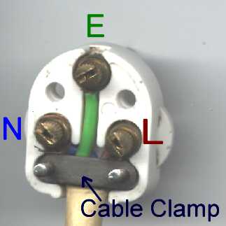
Plunger Controllers A plunger controller should be wired to a plug as follows- NOTE this diagram is for a modern plunger controller - the long obsolete "barrel" controllers from MRRC , VIP or Tradeship must be wired differently see separate diagram . |
|
NOTE - This diagrams omits switches, fuses etc. Click here for the full instructions on track wiring. |
|
The diagram on the left shows how to wire a resistance controller. The plug from on top. The plugs almost invariably have N E and L molded in if you look closely. On the left is the standard for track wiring. The controller should always be wired the same way with the positive (+) side of the power supply going to the controller, and the negative (-) side going direct to the track and brake terminal. The wire colours shown are conventional plug wiring. The important thing is the right pin goes to the correct part of the controller. MRRC controllers always used to have green to N; red to E ; and black to L. For controllers with no brake connection only have two wires, these are connected to the N and L pin, see the section on resistance controllers for more detail. |
|
Trigger controllers should be wired to a plug as follows.
The wire colours shown are standard for Parma controllers. Generally US made controllers come with Croc clips or 4mm banana plugs in the colours shown below. This is because their tracks have 3 separate studs, or 3 separate studs for controller connection rather than the normal British 3 pin plug. When I say British, this is the BSCRA standard, but most non- BSCRA clubs also follow this standard.
Scalextric Sport and Ninco resistance controllers are connected to the track with a jack plug. These are connected as shown . The cable end contact is connected to the power band (L on a BSCRA style plug). The center contact is connected to the the controller wiper (N on a BSCRA style plug). The end contact is connected to the the controller brake band (E on a BSCRA style plug).
|
|
Chokes
A choke (in slot racing jargon) is a device for reducing power to the car. The diagram below shows an example of where to connect an external choke.
|
|
Brake Boxes
Adjustable braking reduces the car's breaking from the full dynamic braking provided by the controller's brake contacts. They can be built into the controller or housed in a separate external box, Often the brake adjustment uses an adjustable resistance of a fraction of an ohm. The diagram below shows an example of where an external brake box is connected.
|
|
Plugs |
|
|
|
|
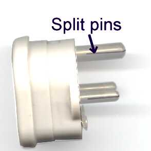
If your plug has a cable clamp us it to clamp the outer insulation of the cable. This reduces the strain on the conductors so will help with reliability. A plug with split pins is better able to accommodate variable or worn sockets. Most plugs have solid pins, but a few minutes with a hack saw can sort that out. Lumps of solder or other solid additions to the pins should be avoided - (a) they don't work as well as split pins and (b) they just stretch the sockets and give everybody else a problem! |
| Ninco also do an electronic controller - the Vario 16. These work very well on Ninco track, so well that lots of drivers want to use them on other sorts of track. Unfortunately various people's attempts to make them work on scratch built tracks have not been successful. Until somebody comes up with a way of interfacing these controllers with other tracks, my advice is that the Vario 16 is only suitable for Ninco track. |
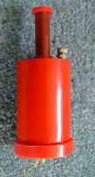
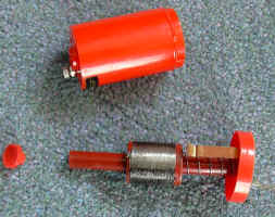
| "Barrel"
type controllers "Barrel" controllers from MRRC , VIP or Tradeship are wired as shown below . This wiring only applies to "Barrel" type controllers, for more Modern plunger controllers see the diagram above. The photos below are of a Tradeship "Barrel" controller, but the other makes look very similar. |
|
|
Copyright © 2000, 2001, 2004, 2009, 2010 C.Frost All rights reserved
No liability is accepted for the information on this site or any use to which it may be put.