Cutting the slots using the "Elliptical Corners" technique
Elliptical corners - what's that
all about? It's a technique for cutting slots used by several
professional track builders. It might be useful if you are building a club
track. The name elliptical seems to have stuck, although the
mathematicians among you will realise that strictly speaking it isn't
elliptical.
The traditional slot cutting technique was to use a straight edge to guide the
router along the straight, and a radius arm or templates to produce the bends.
The straight edges and radius arms had to be set up separately for each slot.
Professional track builders are always looking for a way to do the job more
efficiently and better. This "elliptical" technique means
the shape of the track need only be cut once using straight edges, radius
arms etc. and you then cut the slots using the previous slot to guide the
router. This speeds up the slot cutting, particularly if there are 6 or 8
lanes to be cut, and produces corners that blend into the straight rather than
change from perfectly straight immediately to a fixed radius corner. (The radius
arm method is described on a separate page ).
A quick bit of history - A professional track builder told me all about
this technique in the early 1990s. He asked me not to publish details, so
the series of track building articles I was writing for SCRN at the time didn't
mention it. Although he didn't want to give his
competitors any tips, he was happy for the ideas to be passed on by word of
mouth to help building club tracks . More recently I've found
the technique outlined on some American internet site, who mention it was
invented by Hasse Nilsson. I had a long chat to Hasse when he
delivered the UK8 Nationals track, he told me about a lot about his building
techniques (including elliptical corners) and was happy for me to publish
everything.
How it works
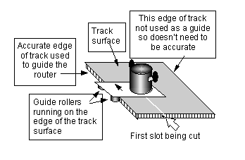
1 Build the track surface in the normal way,
making sure one outer edge is accurate, this edge will act as the guide for the
first slot. This accurate outer edge can use the edge of the board as
delivered or be cut with straight edges guiding a router (or circular saw for
the straight bits). The corners can be cut with a router on a radius arm.
It is important to get a smooth outside edge, any kinks and wiggles will be
reproduced in the line of the slot. By all means use a plane to eliminate
any wiggles. If you have got a slight gap where sheets join then fill it.
It is possible to draw the shape of the curves with a pencil, and use a hand
held jig saw to cut along the line - but inspect this very carefully after
cutting, it'll probably need some work to eliminate small wiggles.
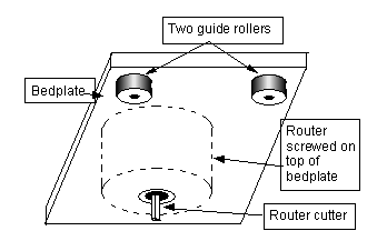
2 Use a jig to cut the first slot using the smooth outer edge of the track
as shown below. The jig is shown with a pair of rollers,
alternatively a pair of solid guide pins can be used. The bedplate
can be made of transparent plastic to make it easier to see what you are
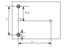
doing, but a cheaper solution is to make it of MDF. I'll explain the
position of the rollers later. Unless you are certain you've got it right
first time, you can cut a very shallow slot first just to make sure its in the
right place. Make it shallower than the braid recess, and you'll have a
second chance to put right any mistakes safe in the knowledge that the mistake
will disappear once the braid recess is cut.
Cutting the first slot using the edge of the track to guide the router


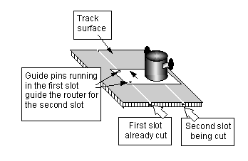
3 Having cut the first slot all the way round the lap, you've got the guide for the second slot. The jig is similar to the roller jig used to cut the first slot, except the two guide rollers are replaced by two guide pins. These pins are the same diameter as the width of the slot and usually made of steel. In fact some builders use the same pin jig for all the slots. Good practice for club tracks is to have the outside slot 150mm / 6 inches (or more) from the track edge in corners and a lane spacing in the range 100 - 110 mm (4 - 4 3/8 in) so you need a different size jig for the two jobs - (or maybe the same jig with alternative router positions). The guide pins fit in the first slot and guide the router to cut the second slot. Once the second slot is cut, repeat the process using the second slot as a guide for cutting the third one - and so on for how ever many lanes you need.
Cutting the next slot using the previous slot to guide the router
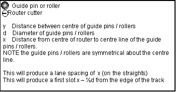
Details of the Router bed plate
 |
 |
So what is this
"Elliptical" shape?
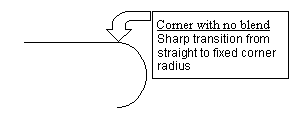
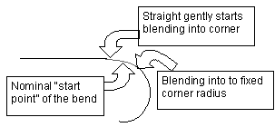
The "elliptical" blending of straight into corners is really quite a subtle effect - you have to look closely to see it on a track and it's even more difficult to illustrate in a diagram. I hope the sketches below gives some idea of what is going on. For example start from the outside of the track cut to a straight followed by a fixed radius corner using a jig with 12 cm pin spacing, the first slot you cut will start to blend in 6cm before the "start point" of the bend and reach the fixed radius 6cm after the "start point " of the bend. The second slot will blend even more gently into the fixed radius corner starting earlier and finishing latter.
 |
 |
Lane spacing using the jig
When you cut a straight, the jig will always maintain the same distance between lane centres. (x on the diagram). When you cut a bend starting on the outside, the jig will cut a slightly larger distance between lane centres. (see diagram). When you cut a bend starting on the inside, the jig will cut a slightly smaller distance between lane centres. The graph (below) shows how much the lane centres change.
|
|
To give an example, take a jig with 12 cm between pins designed to cut 100 mm lane spacing on the straight. Cutting from a 90cm radius bend the graph shows a radius change of 2mm. So working inwards, the next bend would have a 79.8cm radius (102 mm spacing – 2mm more than on the straight) Cutting from the same 90cm radius bend working outwards, the next bend would have a 99.8cm radius (98 mm spacing – 2mm less than you on the straight) .
OK – so what? Well when the radius is large this really doesn’t matter much, indeed most people never notice this has happened. Don’t forget this was developed by builders of raceway style tracks, so they didn’t have much except fairly large radius bends.
From the graph
you can see that with the smallest pin spacing of 10cm the
difference
is only
about 4mm on a 30cm (12 inch) radius bend. So cutting from the outside in you can get down to
an 20 cm (8 inch) radius with the lane spacing increased by 4mm which I guess is OK (and
20 cm radius is fairly tight for a club track). However, working from the 20 cm radius out the lane spacing the
narrowed by over 6mm,
which really isn't desirable. (The graph doesn't go down to corners this tight). Obviously the
geometry works better for small radii bends if the pins are closer together, but
the jig depends on the pins being a reasonable distance apart to guide the
cutter precisely.
So if your track design requires tight bends try to cut the tightest from the
outside in, and if you really cannot avoid going from the inside, perhaps think
about another method for cutting the tightest radii.
Happy building!
Chris Frost
Cutting the slot | Link to next page - Painting and laying Braid / Tape | Link to Track Building start page
This article was originally published in the July 2006 issue of the British Slot Car Racing Association's magazine "Slot Car Racing News" , the internet version has some minor changes
Copyright © 2006 C.Frost All rights reserved
No liability is accepted for the information on this site or any use to which it may be put.