Track Building -
BANKING
How can a banking be designed to avoid cars
launching (and
crashing into one another)?
| Links |
Track Building - BANKING |
|
| BSCRA Home Page | ||
| Track Building index |
|
I've added this section because lots of people read my other articles about track building, and say - hey we want a banked turn in our new track, how do you build it? What shape should the banking be and equally important, what gradients should there be on the straights connected to a banked turn? Looking at my recent e mails, banked turns are very popular in North America right now. Thirty years ago many British club tracks had banked turns - some worked well, but many were plagued with car launching problems on one or more lanes. Perhaps some of the builders at the time understood exactly how to avoid these problems - if they did the knowledge wasn't widespread. Banked turns have just about died out on British club tracks in the last couple of decades. These days "flat tracks" sometimes have a few degrees of banking, often associated with gradients around bridges. Usually the angles involved are too small to generate launching problems. For the rest of these series of articles I have built (or helped build) tracks using the techniques I've described - so I know they work! I haven't built a track with high banked turns myself, but Jim Schneider has. Thanks to Jim both for the photos taken during construction of his track, and for taking the time to check that what I'd worked out in theory does seem to work in practice. There has been some interesting items on the web about building banked bends which show there is more than one way to build a banking. As sometimes happens, the information disappeared from the internet when I was in the middle of writing this article, so I am afraid I cannot give you a link to check it out for yourself! Properly designed bankings shouldn't suffer these launching problems. There are inherent features of banking however clever the design - for example the higher car speeds (higher speeds mean more kinetic energy which increases the risk of damage if it does hit something) and cars being forced down onto the track compressing the rear tyres ( higher g forces are inevitable, this increases the risk of cars touching down and damaging the track so a higher ground clearance more rigidly enforced may be advisable). |
|
Material limitations Slot tracks, including the banked turns, are made of sheet material. How does sheet material like MDF bend into a curve? It will naturally bend it into a single plane curve, but bending it into a two plane curve is much more difficult. There are limits to how tight a bend it will take, and thinner sheet bends more easily than thick sheet. Perhaps I'd better illustrate the difference between single and two plane curves. On the left of the picture are a cone and a cylinder which are single plane curves. On the right are a sphere and a toroid which are two plane curves. If you want a further illustration of the difference, take a sheet of paper and try bending it into the shapes below. |
|
|
|
A banked bend is really just part of a cone, so the flat sheet can be bent to form a gentle banked turn without too much trouble, steeper banking need rather more force, but the basic shape is still the same. One way of producing a banked bend is to cut the turn and the straights either end of it from flat board and then pull the straights together. (Other ways of producing banked bends are discussed below). The diagram below shows how this works. Note that the initial angle between the straights is increased as the straights are pulled together, and that the radius of the bend is simultaneously reduced. |
|
|
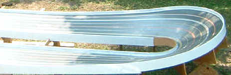
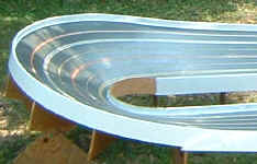
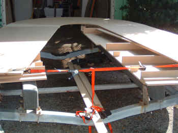
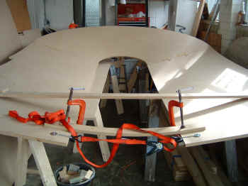
| Jim Schneider built the banked turn on his track using this technique. Here's a couple of photos from Jim showing the turn before (with flat board) and after pulling the straights together (with banking). In this example, the initial angle between the straights is 169°, when the straights were pulled parallel (to 180°) this produced a banking angle of about 20°. Jim tells me that this required a lot of tension on the strap (the red strap in the foreground) and he had to encourage the banking to bend to shape with some radial cuts on the underside. |
|
|
|
This technique isn't particularly new, some 1960's British club tracks had bankings built in this way. For example Tony Condon and Dick Smith remember helping build the North London track banking at the old Church Farm headquarters. This banking was built from chipboard, and the straights were pulled together with a rope. Apparently all that was needed was a lot of tension on the rope and don't worry too much about the groaning noises as it bent! Once the bending was complete, supports were then added to fix the track surface in it's final position. As far as I can remember (I don't suppose anybody can offer a photo - please) it was somewhat steeper than the banking on Jim's track, so it's interesting that "special techniques" to help it bend like the radial cuts or taking it in stages leaving the stresses to relax were not needed. (Click here for more of the story from Dick Smith)
Since originally publishing this article, I've had some other suggestions (1) Bend the track part way then leave it for a week or two, then bend it all the way to the final shape. The builder reports that the mdf cab break trying to get more severer angle all at once, but these can be achieved by doing it in two goes. The forces in the mdf relax with time, it takes up the "bent part way" shape, so by the time you come to bend it to the final shape there is less stress - so it doesn't break.
(2) One builder has suggested that the board should be bent too far, so that it springs back to the right position rather than still trying to move when it's complete. I think a little extra pull should work, but how much? One way I can see of predicting how much extra is by experience of building several tracks - any contributions welcome! The bending stresses in the track surface material will eventually relax, so given time it'll tend to stay somewhere near its new shape. Tracks are not that rigid, so adjustment of the supporting legs can change the banking angles a bit. |
|
There are other ways of building banked turns. Of course a "first hand" story of somebody actually building a banked track deserves more attention than what somebody thinks should work. I cannot quite manage that, but I have found some info on a king track built by Mike Swiss in Chicago, USA. All the turns are banked to some extent, the steepest being at around 36 degrees with the "deadmans" at around 14 degrees. So where is the original info? Good question - it used to be on the "Old Weird Herald" site, but since this has be reorganized I cannot find it anymore. So if you know where this is now, please let me know and I'll put in a link. Bending the surface material Banked turns require the flat MDF sheet to be bent into a curve.. I've already discussed using a strap to pull the MDF into shape, this method is going to work best with bends around 180 degrees. If you want a 90 degree bend it's difficult to see how that would work. Mike used weights (sacks of ballast) on top of the track during construction. These bend the surface to the desired shape for the banked turns. Obviously adding weights will work with any bend angle (not just around 180 degrees). I guess some trial and error will be involved in getting the right amount in the right place. Also care will be needed not to get a dip under the ballast, although the sacks do spread the load over a significant area of the surface. Another method of putting the surface into the required banked profile is a number of tension links to eyes in the floor pulling down the inside of the turn and extra supports lifting the outside of the turn. The screw adjustment of the links allows for fine adjustment of the levels. The tension is applied to the track surface through woodscrews, so this is is more of a point load than a sack of ballast. I guess this is one reason why several links are needed. Although I haven't found an explanation of how they do it some photos show like radial cuts in the underside of the surface at about 4 inch (10cm) intervals, presumably to help the surface bend. On the subject of "special techniques" some people have talked about using steam to soften the board and allow it to bend. Curiously, when asked for more detail, it always turns out this is a story passed on through several people - so I don't know if this is a valuable technique that should be recommended or something that was tried and didn't work (or perhaps somewhere between the two). There was no sign of this on the OWH thread. Is there anybody out there with practical experience of getting all steamed up could tell us how it really works? I guess they must have some sort of support in place while they do this. I think club tracks often had a wooden framework underneath for support. (Other ways of producing banked bends are discussed below). Calculating the bend angles Some builders make a few more degrees of bend than really necessary, then cut to fit. This seems a sound way of doing it, particularly if you haven't got NC machines to make everything precisely as intended. Joining sheets If you are making a small enough radius bend to get the banked turn out of a single sheet, then joining sheets in the middle of a curve isn't necessary. MDF normally comes in 8ftx 4ft sheets (approximately 2.4 x 1.2m). Although larger sheets are available to special order, plenty of track designs require larger bends than the largest available sheet. It is bound to be more difficult to get a smooth joint when bending the MDF round a tighter radius. Tighter radius turns and steeper bankings require the MDF to be bent round a tighter radius. Fortunately when you join sheets of MDF to make a big banking it will inevitable be a large radius turn. Also the car is being forced hard down into the slot, so is less sensitive to the sort of irregularities that might cause it to launch on a flat straight. I have seen photos showing 3 sheets joined to make a large radius bend. In one example the slots were routed with the sheets flat. The only close up photos I've seen show the surface constructed from single thicknesses sheet (not laminated from several layers of thin sheet) . In the finished turn simple triangular supports are used and the sections are joined by tongue and grove joint blocks made of 5 layers of MDF sheet. I have see Ogilvie built baked tracks where the sheets are joined with similar blocks. Some builders complete the whole track with no sidewalls, this allows the angles to be tweaked more easily. In fact some builders braided the track and run cars on it without walls. Running cars round at competitive speed is the ultimate way to check the the surface is angled correctly - and it can still be adjusted it if necessary. I have seen photos of Hasse Nilsson building a track in the 1980s. Hasse is shown routing the surface after it has been bent into the banked shape. Here again the track is constructed without sidewalls, although it is not made clear at what point they were added. It looks like this track is built on the final site, there is no apparent means of dismantling and shipping it (I am not certain about this, but many people have told me that Hasse did build many tracks on site). I know Steve Ogilvie builds tracks in his workshop then dismantles them for shipping to the final site. Steve uses tongue and grove joint blocks made of MDF sheet. Attaching barriers L shaped brackets for barrier attachment are made out of a 2 pieces of MDF. Each bracket is attached to the underside of the track surface with either a single screw and glue or with staples and glue. I've seen this method used by both Hasse Nilsson, Steve Ogilvie and Mike Swiss. Typically the pieces of MDF used for these brackets are about 2 or 2½ inches (5 - 6.5 cm) square. The side walls are then screwed to the L brackets. The side walls stiffen the track surface in its final position. Barriers are normally fitted all the way round both inside and outside. Commercial builders normally use fairly substantial (150 - 180 mm high by 12 mm thick) barriers to the sides of the track, and this seems adequate to hold things in place.
For more information see this OWH thread discussing building banked tracks And another technique... There is an interesting thread on Slot Forum International which shows how the bowls in skateparks are made. These bowls are quite similar to banked turns in slot car tracks. While the radii of the bowls are a bit larger, they are more difficult than slot car bankings because the banking angle gets steeper further up the turn. The supports are more substantial than a slot car banking (no doubt they have to be to stand the weight of what is running on them) and the surface is laminated from several layers of MDF sheet between 3 and 9mm thick to make a 28mm thick surface. The main part of this that wouldn't suit a DIY builder is that the sheets are cut on an NC machine before being laid on the bowl. |
|
What Angle? The principal that what ever angle of turn you have in the flat, you'll have a few more degrees of turn when you bend the surface into a banking is true whatever the angle of the turn. The banking angle that will be produced can be calculated from the initial angle between the straights, so lets give some examples. The "What Banking Angle" graph below shows what banking angle is produced when various initial angles are pulled to 180° (that is till the straights are parallel). The following graphs are theoretical and calculated assuming the banking is a section of a mathematically perfect cone. If you want to calculate it for yourself for any angle, click here. In practice it's questionable how accurately the MDF sheet can be persuaded to follow the "perfect" shape. In fact I'm reasonably optimistic these graphs are a good guide, Jim's track seems to come near to the theoretical values, and I've done small scale tests which come out close to the theoretical values over a range of angles. I'd be very interested to hear from anybody else who has tried building a turn this way.
|
|
|
|
Also there is a reduction in bend radius as shown in the diagram (the same circumference of MDF has got to fit round more degrees of bend so the radius reduces). This reduction in radius is shown in the graph below. (for example with a 25 degree banking the graph shows a reduction of 0.9, so if you stared with a flat turn 1m inside radius and 2 m outside radius, the banked turn would have 1 x 0.9 = 0.9m inside radius and 2 x 0.9 = 1.8 m outside radius) If you want to calculate it for yourself for any angle, click here. |
|
|
| OK - I've described what happens if you pull straights together - what happens if you do the opposite? If the straights are pushed apart to make a smaller angle turn between the straights, the track surface will distort to accommodate it, usually by developing ripples - or should I say bumps - often in the corners. Exactly where these bumps will spring up is difficult to predict - The simple advice is avoid doing this. |
|
The straights This leaves straights going in and out of the banking which are tipped sideways at whatever the angle of the banking is (see Jim's photo above. These straights need to come horizontal to fit with the rest of the track. (Unless you are planning an oval with the corners and straight banked!) The problem that so many banked tracks have suffered from is cars launching. Cars launching problems often originate from convex gradient transitions, as illustrated below. It is all to easy to produce this sort of gradient transition on at least some of the lanes of the straights either side of a banking. For clarity, I've exaggerated the abruptness of the "humps", changes in gradient too gentle to see in an illustration like this can be enough to launch a car - for example if the hump had a radius of 10m (33ft) a car traveling at over 10m/sec (22 mph) would launch (and would be very susceptible to bumps at much lower speeds). |
|
|
| What happens if you build a straight forward conical banking. This is illustrated below. With the axis of the cone vertical, the angle of the banking to the horizontal will be the same all the way round. The straights naturally bend into a shape which provides just the sort of convex hump you don't want. |
|
|
|
A solution this problem is to tip the axis of the banking from the vertical, as shown below. This means the banking is a bit steeper on the right hand side (half way round the curve) than where it joins the straights. Here again the angles in the illustration are exaggerated for clarity. For example a 4 lane track where the straights come flat after 3 m (10 ft), if the track is banked at 20 degrees (angle Y) where it joins the straights, the axis of the cone - angle X - would only need to be tipped at 2 1/2 degrees so the steepest part of the banking would need to be X+Y = 22.5 degrees |
|
|
|
This is a theoretical way of overcoming the launching problem in bankings- I haven't tried building a track like this myself... but I know a man who has. Look closely at Jim Schneider 's photo of his track (below) and you can see all this geometry on a real track. In fact Jim overcame the "hump" problem by increasing the banking angle like this from a practical direction before I'd come up with a theoretical explanation. Obviously the "Concave transition" should be as gentle a curve as possible - if it all happens in a sheet of rather than at the joint between two pieces, the MDF will form a gentle curve naturally. |
|
|
|
Cutting the Slots Since originally publishing this article, I've had some e mails about cutting the slot. It wasn't obvious if it should be done before or after bending the flat sheet to form the banking. It can be seen in the above photos that Jim Schneider bent the track first. However, the piece from Dick Smith makes it clear that at North London the slots were cut first, and the surface bent afterwards. I've had an e mail from another builder saying he tried cutting the slots in flat board, and found he had trouble with the slots narrowing when he bent it into a banking. This suggests it's a better idea to bend the surface into the banked profile first and cut the slot afterwards. The OWH thread shows further examples of cutting before and after bending. It's important to cut the slot accurately, and more complicated / less rigid jigs are obviously not a good idea. Some techniques (such as a radius arm) work best on flat sheet. If the slot is cut from the edge then cutting after bending should work fine. An extra complication of cutting on conical surface is that the router will cut shallow (the outer edges of the router bed will touch the track, but there will be clearance under the centre). This is not a problem for slots which would normally be cut a bit deep anyway, but for braid recesses it may be necessary to adjust the cutting depth in the banked turn. |
|
I know there are other banked tracks being built- so if you trust my theory enough to give it a try, please let me know how well it works out. This web page could certainly do with some practical feedback! If anybody out there has found other ways of arranging banking without accidents - I'd be interested to hear all about it! Chris Frost
|
Copyright © 2003 C.Frost with additions in 2007, 2009 and 2013, Photographs copyright Jim Schneider All rights reserved
No liability is accepted for the information on this site or any use to which it may be put.

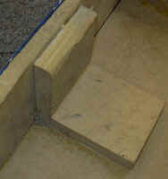 An L shaped bracket in position under a track