|
The Radkovic 1/32 Formula 1 |
|
One of the most successful chassis at National level in recent British racing has been the Radkovic. These are produced by Michal Radkovic from the Czech republic, and come either built or in kit form. Here's a step by step guide to building the kit, and some details of the most successful cars. The construction photos come are of the kit I built recently, I've added some building tips from Brian Saunders.
Chris Frost June 2001
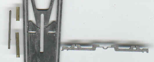
This is how the kit comes. The pans are brass the rest is spring steel.
|
|
|
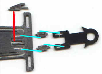
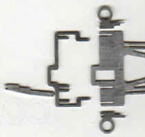
The 2 guide mounting blocks sit up on edge in the cut outs in the chassis and the guide tag sits on top of them with the blocks fitting into the cutouts in the guide tag. (shown with blue lines).
Brian's tip - The two supports for guide plate should be soldered in early in construction, before the front axle support. Once in place use a micrometer to ensure that the 'flats' that the guide plate sit on are all the same height ( side to side most important).
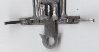
The guide stop (top of photo) fits up on edge into the center part of the chassis (following the red line). The guide tag slides in the slot in the right of the guide stop - this allows side to side movement (up and down in the photo) but hardly any vertical movement. The right hand photo shows it all soldered together.
The above photo shows the front axle parts laid out flat before assembly. The front axle support (the middle piece in the photo) sits up vertically, with the tabs fitting into the cutouts in the front of the chassis (marked by the blue lines. The 0.062 diameter front axle (top) is soldered on top of the 0.062" (1.6mm) thick axle support. The joint between the axle and the support is reinforced. Some builders use brass or steel shim wrapped round the joint, others use wire. Either was the reinforcing is soldered to the axle and support to maximize strength.
Brian's tip To set the front axle up, I solder a .010 inch skid under the front of the chassis on either side. I set the axle width up and put front wheels on it and put it into place before tying it and soldering it. Once done I remove the skids, and hey presto, level axle!!
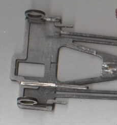
The central pivot is formed with 2 pieces of .079" (2mm) outside dia. brass tube, with a close fitting piece of wire acting as the pivot. (left of photo). The tube I used needed 0.053 wire (it's quite easy to grind down short lengths of wire to the necessary diameter) but the size you use will depend on the bore of the tube. The cross bar (right of photo) fits on its side with the two lugs fitting in the slots in the chassis, and the semi-circular part fitting over the top of the pivot tube. These parts can be seen assembled in the photo below. The rectangular cutouts fairly near the ends on the cross bar take wire pan stops (see diagram below right).
|
|
|
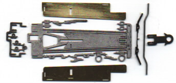
The 4 small steel parts shown in the photo above slot into the 0.040" (1mm) brass pans. The one with the rectangular cut out is the pan stop that will act against the cross bar. The two with circular cut outs are for the body mounting pin tube. The one on the left is a pan shot that rests on part of the back axle brace that projects forward (see photo below - forward is to the right). The diagram (above right) shows a top view of the pans indicating where the pan stops fit.
|
|
|
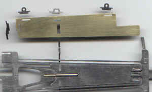
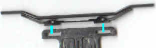
The photos above show the back axle supports. The part on the far left is the motor support. The motor is intended to be soldered to the side of this support and to the main chassis plate by the T shaped cut out.
Here are a couple of pictures of a completed car - this one is Brian Saunders 2000 Haydon open winner originally built by Michal Radkovic. Note the thin lead weight on top of much of the chassis. Also note the thin piece of wire connecting the pans just in front of the cross bar. The lead wire from the motor is enameled copper wire forward to the flexible yellow wire which also serves to self center the guide.
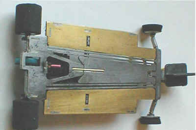 photo by Carl Dale
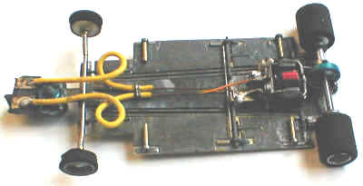 photo by Carl
Dale
photo by Carl
Dale
Motor - The chassis is designed for a strap motor (such as Koford) with a armature length around 0.250". Brian's car had a 40 turns of 28 gauge 0.480" diameter armature at Haydon. At the 2001 Nationals there were 4 of these chassis in the final. The hottest motor was Steve Kearey who was running 35 turns of 27 gauge (and found it worked best with some choke). The coolest was George Kimber with 45 turns of 30 gauge.
Gearing - Brian has this one on 8:31 Sonic Plastic gears at the Haydon open, more recently he's been using a 6 tooth pinion.
Brian's tip The 6t and 7t pinions (1.5mm bore) I use are both 80dp. The gear diameter is limited to 13mm, so choice is a bit limited. I have 30 (plastic), 31 or 32 sonic custom. Also there are 31 and 32 plastic, but need reducing in diameter, which is quite easy. The Cahoza plastic are not readily available so don't get used very often.
Weight - The 4 cars in the 2001 National final weighed 90gm (Steve Sargent) 82gm ( George Kimber) 78gm (Brian Saunders) and 74gm (Steve Kearey).
Copyright © 2001 British Slot Car Racing Association All rights reserved
No liability is accepted for the information on this site or any use to which it may be put.