
|
BSCRA |
|
Slot Racing History |
|
ECRA / BSCRA Origins |
|
|
|
Slot Racing 1942 Style
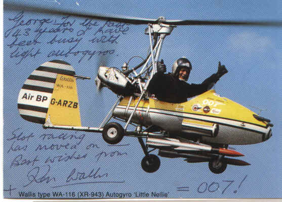 |
Ken Wallis’ exploits in 1942 will come as a surprise if you thought slot racing was only 40 years old. Ken got in touch with George Kimber ( BSCRA Chairman at the time) following some BSCRA publicity. Aviation enthusiast will no doubt know all about Ken’s development of lightweight autogyros, which came to the attention of an even wider public when they starred in a James Bond film. Much less well known is his development of what started out as a rail racing system, and was soon developed into slot racing. Enough from me – I’ll let Ken tell the first part of his slot racing story. Chris Frost |
Before World War 2, I was interested in making "Special" cars, using Austin 7, Bentley & Invicta chassis. When in the R.A.F. during WW2 this was hardly a practical hobby to be conducted in one's spare time, while living in a small room in a hut on the Station. Always interested in models, and having had model railways, it occurred to me that model racing cars could be more exciting than model railways. Accordingly, in 1942, having completed my first "tour" of Bomber operations, while on the Staff at No 21 Operational Training Unit at Moreton-in-the-Marsh I started making my first experiments.
The cars would necessarily be very small, since only a small track could be considered. Very small electric motors were not then available, so I had to make my own, with 3 pole armatures only 5/16"' diameter, and using watch gears to drive the rear axles. The commutators were made from a piece of nickel bonze brazing rod, suitably drilled to accept an insulating tube over the armature shaft. Then three cuts would be made along the "tube" that had been formed at the end of the brazing rod, to form the commutator segments. A suitable insulating sleeve would then be placed over a part of the cut commutator, and the assembly would then have the extended ends bent up for wiring connections and whole assembly, (still part of the brazing rod) would be forced into place on the armature shaft. Only when in place would the commutator segments be carefully sawn off the rest of the brazing rod which kept everything in place during assembly. This was quite a fiddle job!
The first experiments were with a wire on the surface of the track and an inverted "U" follower linked in with the Ackerman steering of the front wheels. It also served as an electrical pick-up. Copper wire was set in the tyres of the rear wheels to make contact with metal foil stuck beside the guide wire to complete the circuit. With this system, acceleration and some wheelspin would be accompanied by a shower of sparks!
The little cars employed a metal "chassis", with the bodywork of "Perspex" from crashed aircraft, suitably heated & moulded to shape. They represented the cars of the Thirties. They were about 2 ½" long.
|
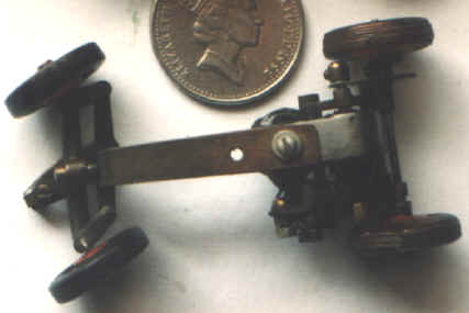
The Rail Guided Car
Top and bottom view of One of the original 2 "rail" guided cars. At the front is the inverted U arm, for steering the model by following a wire laid on the track. One electrical contact was in the U arm, the other contact was by copper wire round the rear wheel - these can be seen in the photo. The steering system restricted the amount that the car could "spin" on a corner. The pin in the slot system soon replaced it |
However, the surface wire guidance was sometimes subject to damage when the little cars spun out of control. I soon replaced it with a slot cut in a sheet of plywood track, the slot being made by use of a dentist's drill driven by an electric motor adapted from a Gunsight Aiming Point camera. A pin forward of the steering axis of the "offside" front wheel would engage in the slot and steer the front wheels as the car moved forward. This "pin following a slot" system was far superior to the first experiment, in that the cars could swing round completely without any damage to the track or the car.
My first two slot racing cars were soon racing, on a track constructed on a "black-out" board" for our hut. (Such plywood was not readily available in 1942, but the use of a black-out board confined the racing to daylight hours!)
Aircraft instrument lighting dimmer switch rheostats, also from crashes, were fitted with a "accelerator pedal" lever, mounted on the side of the track (to act as a controller).
This was all in the 1942/'3 period and activities necessarily ceased when I went back on operations, this time in Italy. I still have the cars, but the original track is long gone.
I certainly send my best wishes to members of the British Slot Car Racing Association. At the age of 87 1 am, not likely to offer any serious competition by taking up slot car racing again!
Kenneth E. Wallis
|
|
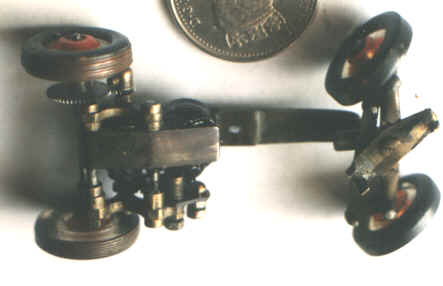
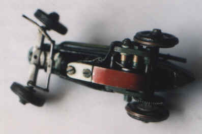
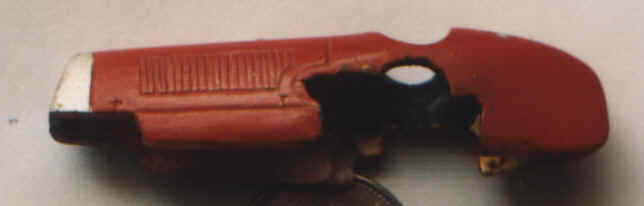
The Slot Car The underside of the car showing the guide pin forward of the "port" wheel (top left of photo). Apparently this worked well. Having the slot offset to one side of the car looks unusual compared with modern cars. This one was converted from a rail guided car - the fixing holes for the guide can be seen in the middle of the steering arms. The photo shows the copper wire on the outside of both rear tyres for electrical contact with the metal foil on the track. The body (below) of the cars were made from Perspex recovered from crashed aircraft. The cars were only 2 ½ inches long – about HO size. |
|
|
|
Originally published in the March 2004 edition of the BSCRA magazine "Slot Car Racing News"
A second article covering Ken's slot racing developments from 1945 through 1957 appeared in the May 2006 edition of "Slot Car Racing News"
© Copyright British Slot Car Racing Association 2004 All rights Reserved All photographs are copyright Kenneth E. Wallis